Description
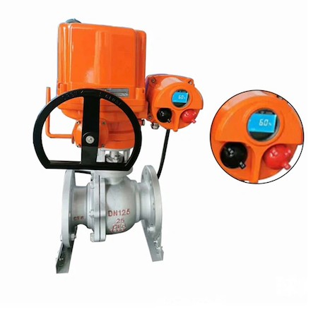
The DN125 Electric CF8 A351 Ball Valve is a sphere with a circular channel, which rotates around an axis perpendicular to the channel. The ball rotates with the valve stem to achieve the purpose of opening and closing the channel. The ball valve only needs to be rotated 90 degrees and a small rotational torque to close tightly. When the ball valve rotates 90 degrees, all spherical surfaces should be present at the inlet and outlet. Thereby closing the valve and cutting off the flow of the medium.
Introduction
The opening and closing part (ball) is driven by the valve stem and rotates around the axis of the ball valve. It can also be used for the regulation and control of fluids. The hard-sealed V-port ball valve has a strong shear force between the V-port ball core and the metal valve seat with hard alloy surfacing. It is especially suitable for materials containing fibers and tiny solid particles. etc. media. The multi-way ball valve can not only flexibly control the confluence, divergence, and flow direction switching of media on the pipeline, but can also close any channel and connect the other two channels. This type of valve should generally be installed horizontally in pipelines. Ball valves are divided into pneumatic ball valves, electric ball valves and manual ball valves according to the driving mode.
Installation and maintenance
1. When the electric ball valve is closed, there is still pressurized fluid inside the valve body;
2. Before maintenance, release the pipeline pressure and keep the valve in the open position; disconnect the power or air source; disengage the actuator from the bracket;
3. It is necessary to confirm that the pressure in the upstream and downstream pipelines of the electric ball valve has been relieved before disassembly and disassembly can be carried out;
4. When disassembling and reassembling, care must be taken to prevent damage to the sealing surfaces of parts, especially non-metallic parts. Special tools should be used when removing the O-ring;
5. During assembly, the bolts on the flange must be tightened symmetrically, gradually and evenly;
6. The cleaning agent should be compatible with the rubber parts, plastic parts, metal parts and working media (such as gas) in the ball valve. When the working medium is gas, gasoline (GB484-89) can be used to clean metal parts. Clean non-metal parts with pure water or alcohol;
7. The decomposed individual parts can be cleaned by dipping. Metal parts that still have undecomposed non-metallic parts can be scrubbed with a clean, fine silk cloth soaked in cleaning agent (to prevent fibers from falling off and adhering to the parts). During cleaning, all grease, dirt, glue, dust, etc. adhering to the wall surface must be removed;
8. Non-metal parts should be taken out of the cleaning agent immediately after cleaning and should not be soaked for a long time;
9. After cleaning, it is necessary to wait for the cleaning agent on the wall to be washed to evaporate (it can be wiped with a silk cloth not soaked in cleaning agent) before assembly, but it must not be left aside for a long time, otherwise it will rust and be contaminated by dust;
10. New parts also need to be cleaned before assembly;
11. Use grease for lubrication. Grease should be compatible with ball valve metal materials, rubber parts, plastic parts and working media. When the working medium is gas, special 221 grease can be used. Apply a thin layer of grease on the surface of the seal installation groove, apply a thin layer of grease on the rubber seal, and apply a thin layer of grease on the sealing surface and friction surface of the valve stem;
12. During assembly, metal chips, fibers, grease (except those specified for use), dust and other impurities, foreign matter, etc. should not be allowed to contaminate, adhere to, or stay on the surface of the part or enter the inner cavity.
The working principle of ball valve
The opening and closing part of the ball valve is a sphere with a circular channel, which rotates around an axis perpendicular to the channel. The ball rotates with the valve stem to achieve the purpose of opening and closing the channel. The ball valve only needs to be rotated 90 degrees and a small rotational torque to close tightly. According to the needs of working conditions, different driving devices can be assembled to form ball valves with various control methods, such as electric ball valves, pneumatic ball valves, hydraulic ball valves, etc.
When the ball valve rotates 90 degrees, the inlet and outlet should all present spherical surfaces, thereby closing the valve and cutting off the flow of the medium.
Types and classifications
A ball valve is a valve with a ball as a closing member. It is mainly composed of a valve body, a valve seat, a ball, a valve stem, a handle (or other driving devices, such as electric actuators, pneumatic actuators or hydraulic actuators). The valve stem drives and rotates around the axis of the ball valve. It is mainly used to cut off, distribute and change the flow direction of the medium in the pipeline.
There are many types of ball valves, including different working principles, media used, and application locations. Users should choose different types of ball valves according to the working conditions. The types of ball valves are classified according to the actual working conditions on site.
Why did there be an explosion?
An explosion is when matter suddenly changes from one state to another state after physical or chemical changes, and releases huge amounts of energy. The energy released at a rapid speed will cause violent impact and damage to surrounding objects. Three conditions must be met for an explosion: explosive material, oxygen, and ignition source. Objectively speaking, many industrial sites meet explosion conditions. When the mixed concentration of explosive substances and oxygen is within the explosion limit range, if an explosion source exists, an explosion will occur.
To prevent the occurrence of explosions, we must consider the above three necessary conditions. Limiting one of the necessary conditions will limit the occurrence of explosions. Electrical equipment is also a potential source of ignition, causing surface temperature to rise, electrostatic discharge or sparks caused by instantaneous current when the machine is running. In terms of design, flameproof electrical equipment can seal the ignited explosive mixture in a shell. The shell is particularly strong and can withstand the explosion pressure of the explosive mixture inside and prevent the explosive mixture from propagating to the outside of the shell. Flameproof electrical equipment therefore prevents it from becoming a potential source of ignition.


