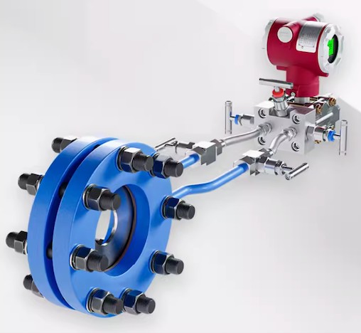
Description
The integrated orifice flowmeter consists of a standard orifice plate and a multi-parameter transmitter. In metallurgy, chemical industry, petroleum, electric power industry system continuous measurement medium temperature ≤400℃ liquid, gas, steam flow, transmitter can directly display the current instantaneous flow meter, cumulative amount, temperature, pressure and other parameters. The transmitter can convert the instantaneous flow signal into a proportional 4-20mA analog signal output.
INTRODUCTION:
When the fluid filled with the pipeline flows through the throttling device in the pipeline, the flow beam will form a local contraction at the throttling part of the throttling device, so that the flow rate increases the static pressure is low, so that the pressure drop is generated before and after the throttling part, that is, the greater the flow rate of the medium flow, the greater the pressure difference generated before and after the throttling part. So you can measure the size of the fluid flow by measuring the pressure difference. This measurement method is based on the law of preservation and the law of flow continuity.
Intelligent throttling device (orifice flowmeter) is a new generation flowmeter that integrates flow, temperature and pressure detection functions and can automatically compensate temperature and pressure. The microcomputer technology and micro-power consumption technology adopted by the device have strong function, compact structure, simple operation and convenient use.
1. Use
The LG/FB standard ring chamber orifice and flange orifice orifice throttling device is a non-graduated flow measurement device, which is used with pneumatic, electric differential pressure transmitter or double bellows differential pressure transmitter. In the metallurgical, chemical, petroleum, electric power industry system continuous measurement medium temperature ≤ 400 ℃ liquid, gas, steam flow through the hole plate generated by the pressure difference, the transmitter will be the pressure difference signal into a proportional output signal, and then a secondary instrument or regulator, the measured flow is recorded, indicated or adjusted.
Second, basic principles
The orificule or nozzle and other throttling parts are installed inside the pipe. Because the aperture of the throttling parts is smaller than the inner diameter of the pipe, when the fluid flows through the throttling parts, the beam section will shrink suddenly and the flow rate will be accelerated. The static pressure of the fluid at the back end of the throttling part is reduced, so that the static pressure difference before and after the throttling part is generated (see Figure 1). There is a definite numerical relationship between the static pressure difference and the fluid flow through the fluid, which is consistent with Q=K. The square root of △ P. Use differential pressure transmitter (or differential pressure meter) to measure the differential pressure before and after the throttle to measure the flow rate.
Three, installation requirements
The installation of the throttling device is related to the following pipe sections and fittings: the No. 1 resistance part and No. 2 resistance part on the upstream side of the throttling part, the No. 1 resistance part on the right side of the throttling part, the pipe section between the No. 2 resistance part upstream of the throttling part and the No. 1 resistance part downstream, and the differential pressure signal pipeline.
