Description
The Electric Motorized O Type Cut-off Ball Valve is a 90°rotating ball valve with excellent sealing performance, large flow capacity, small flow resistance coefficient, simple structure, convenient maintenance, long service life, and the valve body passage and link pipe diameters are equal and form one diameter. The medium flows through almost without loss. It is equipped with an actuator.
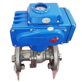
Actuator Product features
Shell - The shell is made of hard aluminum alloy, anodized and polyester powder coated, with strong corrosion resistance. The protection level is IP67, NEMA4 and 6, and IP68 type is available.
Motor - fully enclosed squirrel cage motor, small size, large torque, small inertia force, insulation grade F, built-in overheating protection switch to prevent overheating damage to the motor.
Handle structure - the design of the handle ensures safety, reliability, labor saving and small size. When power is off, pull the handle for manual operation. When not using it manually, place the wrench in the wrench clip for easy use.
Indicator--The indicator is mounted on the central axis and allows the valve position to be observed. The lens adopts a convex mirror design, which does not accumulate water and makes observation more convenient.
Dryer - used to control the temperature, prevent moisture condensation inside the actuator due to changes in temperature and weather, and keep internal electrical components dry.
Sealing - good sealing, standard product protection level is IP67, and IP68 protection level is optional.
Features of O-Type Cut-off Ball Valve
The electric O-type cut-off ball valve is a 90°rotating ball valve with excellent sealing performance, large flow capacity, small flow resistance coefficient, simple structure, convenient maintenance, long service life, and the valve body passage and link pipe diameters are equal and form one diameter. The medium flows through almost without loss. It is equipped with an actuator. The product is usually used in occasions with strict sealing requirements. In addition to controlling gas, liquid, and vapor media, it is also suitable for controlling room water containing fibrous impurities. It is widely used in petroleum, chemical industry, metallurgy, light industry, papermaking, power station, refrigeration and other working field.
Electric ball valve structure
There are many types of electric ball valves. They are generally divided into two categories according to their structural forms, namely O-type structure and V-type structure. The ball openings of the two are different and their applications are also different. The O-type is generally suitable for shut-off use and occasional adjustment. , while the V-type is more suitable for adjustment (larger adjustable ratio).
O-type ball valve structure: The O-type ball valve has a ball with a middle through hole installed inside the valve body. The ball has a through hole with a diameter equal to the diameter of the pipe. When fully open, it is a non-blocking valve with large flow capacity and no directionality of fluid entering the valve. The ball can rotate in the sealing seat, and there is an annular elastomer on both sides in the direction of the pipeline to achieve sealing. By rotating the ball 90°, the direction of the through hole can be changed, thereby realizing the opening and closing of the ball valve.
V-shaped ball valve structure: The ball core of the V-type ball valve has a V-shaped structure. The valve core is a 1/4 spherical shell with a V-shaped notch. As the ball rotates, the opening area changes, but the shape of the opening surface always remains triangular, and the flow characteristics are similar to others. Percent, adjustable ratio is large. It has the characteristics of large flow capacity, large adjustable range, shear force, and tight closing ability. It is especially suitable for working conditions where the fluid material is fibrous. Generally, V-shaped ball valves are single-seal ball valves. Not suitable for two-way use.
Operation and use of electric flange ball valve
1. Make sure the pipelines and valves have been flushed before operation.
2. The operation of the valve is completed by rotating the valve stem (manual or automatic control mode): when rotated 1/4 turn (90°) clockwise, the valve is closed. When rotated 1/4 turn (90°) in the opposite direction, the valve opens.
3. When the groove direction at the top of the handle or valve stem is parallel to the pipeline, the valve is open.
4. The torque of the valve stem will vary depending on the following factors: the length of time the valve opens and closes, the medium of the pipeline system, the pipeline pressure and the type of valve seat, etc.


